Virtual Memory and OS
Things covered so far:
- CPU
- Caches
Things not covered so far:
- Memory
- I/O
Intro to OS
- OS is the (first) thing that runs when computer starts
- Start services
- fs, network, tty...
- Start services
- Provides interaction with the outside world
- Finds and controls all devices in the machine in a general way: Relies on hardware specific “device drivers”
- Loads, runs and manages programs:
- Isolation: Each program runs (i.e., appears to run) separately, and thinks it has the control of all the resources.
- Resource-sharing: Multiple programs share the same resources:
- Memory
- I/O devices: disk, keyboard, display, network, ...
- Time-sharing: Processor (CPU) runs multiple processes.
Multiprogramming: running multiple applications (processes) "simultaneously" on one CPU
- The OS manages mulitprogramming
- Achived via OS context switches, switches between processes very quickly:
- Save current process state (program counter, registers, etc.)
- Load next process state to execute next instruction on CPU
- Do not switch out data between main memory and disk (costly)
Physical Memory and Disk Storage
Main memory: DRAM
- Dynamic Random Access Memory
- Latency to access first word: ~10ns, ~30-40 clock cycles Each successive (0.5ns - 1ns)
- Each access brings 64 bits, 'burst access' (multiple access at one time)
- Expensive
- Data is impermanent
- Dynamic: capacitors store bits, so needs periodic refresh to maintain charge
- Volatile: when power is removed, loses data.
- Contrast with SRAM
- Static (no capacitors) but still volatile
- Faster (0.5 ns)/more expensive/lower density
Second memory: Disk, SSD
- Attached as a peripheral I/O device (non-volatile)
- Solid-State Drive (SSD)
- Access: 40-100 μs (~100k cycles)
- Cheap
- Hard Disk Drive (HDD)
- Access: < 5 - 10 ms (10-20M cycles)
- Cheaper
Virtual Memory and Virtual Addresses
- What if main memory is smaller than the program address space?
- 32-bit systems: 4 GiB addressable memory
- But only 1 GiB RAM
- What if two programs access the same address address?
- Overwriting each other: Data corruption
- Need protection
Virtual memory is the next level in the memory hierarchy
- Give each process the illusion of a full memory address space that it has completely for itself.
- Under the hood: working set of pages reside in main memory; other pages are in disk.
Benefits:
- Demand paging provides the ability to run programs larger than the primary memory (DRAM)
- OS can share memory and protect programs from each other.
- Hides difference between machine configurations
Address Space: set of addresses for all available memory locations
- Virtual Address Space
- Set of addresses that the user program knows about
- Physical Address Space
- Set of addresses that map to actual physical locations in memory
- Hidden from user applications
- For each program, a memory manager maps (translates) between Virtual and Physical address spaces
- Processes use virtual addresses
- Many processes, using same (conflicting) addresses
- Memory uses physical address
- Processes use virtual addresses
OS Virtual Memory Management Responsibilities
- Map virtual addresses to physical addresses
- Use both memory and disk
- Give illusion of larger memory by storing some content on disk.
- Disk is usually much larger and slower than DRAM.
- Protection
- Isolate memory between processes.
Paged Memory
Concept of "Paged Memory":
- Physical memory (DRAM) is broken into pages.
- A disk access loads an entire page into memory. (swap)
- Typical page size: 4 KiB+ (on modern OSs)
- Need 12 bits of page offset to address all 4 KiB bytes.
If virtual and physical pages are the same size, then memory translation only need to map Virtual Page Number (VPN) to a Physical Page Number (PPN)
Virtual address
       |VPN (20 bits)|offset (12 bits)|
Physical address  |
   |PPN (36 bits) V  |offset (12 bits)|
Translation: Accessing Memory
- Program executes a load specifying a virtual address (VA)
- Computer translates VA to the physical address (PA) in memory.
- Extract virtual page number (VPN) from VA
- e.g., top 20 bits of page size 4KiB = 2^12 B
- Look up physical page number (PPN) in page table
- Construct PA: physical page number + offset (from virtual address) (concat)
- Extract virtual page number (VPN) from VA
- If the physical page is not in memory, then OS loads it in from disk.
- Load the page into memory
- Update the page table to map the loaded PPN to the VPN
- The OS reads memory at the PA and returns the data to the program.
     Program              Page Table          DRAM
32-b virtual           |  VPN  |  PPN  |   physical address space
address space          |  ...  |  ...  |  |      ...      |
                       |0x60000| disk  |  |    data for t0|
lb t0, 0xFFFFF001(x0)  |  ...  |  ...  |  |               |
                       |0xFFFFF|   1   |  |               |

     Program              Page Table          DRAM
32-b virtual           |  VPN  |  PPN  |   physical address space
address space          |  ...  |  ...  |  |      ...      |
                       |0x60000|   2   |  |    data for t0|
lb t0, 0xFFFFF001(x0)  |  ...  |  ...  |  |    data for t1|<---disk read
lb t1, 0x60000030(x0)  |0xFFFFF|   1   |  |               |
                                   ^update page table
Page Table
Page table look up: Index - Physical page number KV pairs One page table per process:
- One entry per virtual page number
- Number of entries: (virtual address number) / (page size)
- Each entry:
- Status bits
- Physical page number / disk address mapped to
- A page table is a lookup table (contains no data)
- All VPNs have a valid entry
- like cache index
- no tags
Protection with Page Tables
- Each process has a dedicated page table
- OS keep track of which process is active
- Isolation: Assign processes different pages in DRAM
- Prevents accessing other processors' memory
- Page tables managed by OS
- Sharing is also possible:
- OS may assign some physical pages to several processes
- e.g., Read-only system data
- Page Table Entry includes a write protection bit (read-only)
- If on, then the page is protected
- e.g., text segment, system data
- Writing to a protected page triggers an exception (handled by OS)
- If on, then the page is protected
Page Table Functionality
Page tables are stored in memory
- Each process needs a page table, so too large for cache
- On memory access cache miss, two (slow memory accesses)
- First access page tabe in main memory to translate to PA
- Then read physical page in main memory
Performance of Page Tables:
- Transfer blocks (not words) between DRAM and processor cache
- Use a cache for frequently used page table entries
Page Faults
Page table entries store status to indicate if the page is in memory or only on disk
- On each memory access, check the page table entry “valid” status bit.
- Valid -> In DRAM
- R/W data in DRAM
- Invalid -> On disk
- Triggers a Page Fault; OS intervenes to allocate the page into DRAM.
- If out of memory, first evict a page from DRAM.
- Store evicted page to disk.
- Read requested page from disk into DRAM.
- Finally, read/write data in DRAM.
The page replacement policy (e.g., LRU/FIFO/random) is usually done in OS/software; this overheard << disk access time.
- OS perform page replacement whilest accessing the disk
Page Table Status Bits
- Write protection bit
- On: If process writes to page, trigger exception
- Valid Bit
- On: Page is in RAM
- Dirty Bit
- On: Page on RAM is more up-to-date than page on disk
Write Policy with Page Table
Always write-back (disk accesses too long)
On page fault (invalid, data to read is on disk):
- Retrive data page (to load in)
- Update page table
On page eviction (memory is full, need new page into memory):
- Write back to disk
Hierarchical Page Tables
Page tables are too large if too many processes -> Page Table Hierarchy
- Multilevel page tables with decreasing page size
- Key: Sparsity of Virtual Address Space use. Most program use only a fraction of virtual memory, many page tables are not accessed
- Level 1 page table always in DRAM
- Level 2 page tables can be in disk; loaded into DRAM via L1 access
Example: 32-bit virtual memory address space, 4 GiB DRAM, 4 KiB pages:
- Page table entry size is 4 B for all levels of page tables.
- RV32I 2-level mapping:
virtual 31          22 21          12 11         0
address| L1 index (10)| L2 index (10)| offset (12)|- Page Table Register (SPTBR) stores the address of the L1 page table
SPTBR
  Root of current L1 Page Table

DRAM
  Level 1 page table - 2^10 entries:
    - PPN for Level 2 page table
    - Status bits
  Level 2 page tables - 2^10 entries:
    - PPN for data page table
    - Status bits
  Data pages...

Disk
  L2 page tables
  Data pages
Compare:
- 1-level page tables takes up 4 MiB each process
- 2-level page tables takes up 4 KiB for L1, more in disk
Page Table Translation
Given a virtual memory address, first divide the address into three parts:
- L1 index (10 bits)
- L2 index (10 bits)
- Offset (12 bits)
Steps taken to translate:
- Look up the L2 Physical Page Number in L1 Page Table at the L1 index
- L1 page table stores L2 Physical Page Number in each of its index
- You can imagine there're no offset, page tables occupies whole pages
- If in disk, load L2 from disk, update L1
- Now we have L2 PPN
- L1 page table stores L2 Physical Page Number in each of its index
- Go to the L2 Page Table, look up the Data Page Number in L2 Page Table at the L2 index
- If in disk, load Data page from disk, update L2
- Now we have Data PPN
- Finally, concat Data PPN + Page offset to get Physical Address
OS Boot
OS Exceptions
Supervisor Mode & User Mode
- CPUs have a hardware supervisor mode (kernel mode)
- Set by a status bit in a special register.
- An OS process in supervisor mode helps enforce constraints to other processes, e.g., access to memory, devices, etc.
- (
suin hardware)
- In user mode, a process can only access a subset of instructions and physical memory
- Can change out of supervisor mode using a special instruction (e.g.
sret). - Cannot change into supervisor mode directly; instead, HW interrupt/exception.
- The OS mostly runs in user mode, need to be careful with Supervisor mode
- Can change out of supervisor mode using a special instruction (e.g.
Exceptions and Interrupts
Exceptions
- Caused by an event during the execution of the current program.
- Synchronous; must be handled immediately.
- Examples
- Illegal instruction
- Divide by zero
- Page fault
- Write protection violation
Interrupts
- Caused by an event external to the current running program.
- Asynchronous to current program; does not need to be handled immediately (but should be soon).
- Examples:
- Key press
- Disk I/O
Exception Handling
The Trap Handler is software that services interrupts/exceptions.
Workflow:
- Complete all instructions before the faulting instruction
- Flush all instructions after the faulting instruction
- Convert to
nops, bubbles - Flush faulting instruction
- Convert to
- Transfer execution to trap handler (in supervisor mode)
- Optionally return to the original program and re-execute instruction
- Program backs to normal as nothing happened
Trap Handler workflow:
- Save the state of the current program
- Save all the registers, PC, Page Table Reigster
- Determine execption/interruption type
- Inferred by faulting instruction and its current pipeline stage, e.g.:
- IF/ID: PC address exception
- ID/EX: Illegal opcode
- EX/MEM: Data address exception
- Inferred by faulting instruction and its current pipeline stage, e.g.:
- Handle exception/interruption, then do one of the two things:
- Continue execution of the program 4. Restore program state 5. Return control to the program
- Terminate the program 4. Free the program resources 5. Schedule a new program
- Depending on the type of Exception (IO, trap/syscall, fault), the handler returns control to either I+0 or I+1, more on [[CSAPP/Exceptional Control Flow/Exceptions]]
Handling Context Switches
Context Switches
- OS switches between processes by changing the internal state of the processor.
- Allows a single processor to “simultaneously” run many programs.
Procedures of context switches:
- The OS sets a timer. When it expires, perform a hardware interrupt.
- Trap handler saves all register values, including:
- Program counter (PC)
- Page Table Register (SPTBR in RV32I)
- The memory address of the active process's page table
- Trap handler then loads in the next process’s registers and returns to user mode.
All other processes are in DRAM, until the trap handler load their registers into CPU and return to user mode.
Handling Page Faults
Page faults: An accessed page table entry has valid bit off -> data is not in DRAM.
Page faults are handled by the trap handler
- The page fault exception handler initiates transfers to/from disk and performs any page table updates.
- If pages needs to be swapped from disk, perform context switch so that another process can use the CPU in the meantime.
- A "precise trap" so that resuming a process is easy.
- Following the page fault, re-execute the instruction.
System Calls
A system call (syscall) is a "software interrupt" that envokes the trap handler, allowing a program to request a service from the OS
- In the form of function call, executed by kernel
- Examples
- File I/O, file system operations
- Accessing external devices
printf,malloc, (ecallsin RISC-V)- Launch a new process
Launch a new process from a process:
- Shell forks: a syscall that traps into the OS kernel process
- OS (supervisor mode): Load program (see CALL); jump to start of main. Return to user mode.
- Shell: “wait” for main to return (join)
Caches and Virutal Memory
Blocks, pages, (bytes, words) are all units of memory
- Cahces: blocks
- ~64 B
- Memory:pages
- ~4 KiB
Functionality
- Cache
- Data at each level is a quick-access copy of data at a lower level in the memory hierarch
- Page Table
- Translates address, store physical page numbers
- Facilitate Demanding Paging
- Cache data pages in memory.
- Access disk pages only on demand by the process.
- Page Table keeps track of page status/location.
| Caching | Demand Paging | |
|---|---|---|
| Memory Unit | Block | Page |
| - Size | 32B to 64B | 4KiB to 8KiB |
| - Misss | Cache Miss | Page Fault |
| Associativity | Direct-mapped N-way Set associative Fully associative | Fully associative (disk pages can be placed anywhere) |
| Replacement policy | LRU or random | LRU, FIFO, random |
| Write policy | Write-through / write-back | Write-back |
Translation Lookaside Buffer (TLB)
Virtual Memory = address translation + protection + demand paging Effect of Virtual Memory: the illusion of a large, private, and uniform storage
- Privacy means Protection:
- Several users/processes, each with their own private address space.
- Uniform storage means Demand Paging
- The ability to run programs larger than primary memory (DRAM).
- Hides difference in machine configurations.
Price: Address translation on each memory reference, increase AMAT
- Virtual Memory should be fast (~1 clock cycle) and space efficient
- Every instruction/data access needs address translation.
- But page tables are in memory, every instruction/data access needs a page table walk
- Single level page table: 2 memory accesses
- Two level page table: 3 memory accesses
- Solution: Cache some translations in the Translation Lookaside Buffer (TLB)
The Translation Lookaside Buffer (TLB) caches page table entries:
- TLB hit: Single-cycle translation
- TLB miss: Page table walk to refill TLB
VA |    VPN    | offset |
         |            |
TLB------V---------   |
|V|D|TLB tag| PPN |   |
-------------------   |
| | |       |     |   |
| | |       |     |   |
-------------------   |
    miss|      |hit   ----------------------
        |      |                           V
        V      ------------> |   PPN   | offset | Physical Address
Page Table Walk- Valid/Dirty bit
- 16 KiB pages
- 40-bit VA
- 64 GiB physical memory
- 2-way set associative TLB with 512 entries
16 KiB pages -> 14 bit Page offset -> VPN = 26 bits 64 GiB memory -> 36 bit PA -> PPN = 22 bits 2-way 512 entry TLB -> TIO: 18/8/14 -> TLB Tag = 18 bits
Layout: 45 bits
- Valid: 1 bit
- Dirty: 1 bit
- Ref: 1 bit
- Reference bit: Reference
- Access rights: 2 bits
- TLB TAg: 18 bits
- PPN: 22 bits
TLB Tag, Index, Offset
The TLB is indexed by the Virtual Page Number
Virtual Address split up:
VA | TLB tag | TLB index | offset | < Page offset
|<--------VPN-------->|- TLB index/tag is used just like in a cache
- Index for the entry index (position) in TLB
- Tag for matching entries
- TIO for VA and PA are unrelated
- VA: TLB tag, TLB index, Page offset
- PA: Cache tag, Cache index, (Cache) Block offset
Memory Access with TLB
- We assume Physically Indexed, Physically Tagged caches
- TLB first, then cache (VA -> PA)
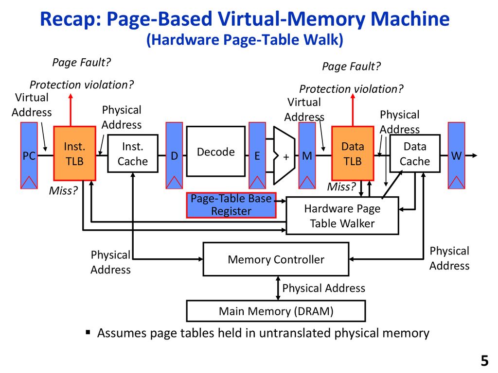
TLBs in the Datapath
+-----+         +-------+      +------+      | \              +-------+
| PC  |->Inst.->| IMEM  |->IF->|Decode|->ID->|  \   EX->Data->| DMEM  |->MEM
|     |   TLB   | Inst. |  /   +------+  /   >EX|-> /   TLB   | Data  |   /
+--^--+    |    | Cache |  ID            EX->|  /   MEM  |    | Cache |  WB
V +-------+ ^ ^ | / V +-------+ ^- Each instruction/data access = address translation + functional checks
- Handle:
- TLB Miss: Needs a mechanism to refill TLB (usually done in hardware).
- Page Fault
- Needs a precise trap so that software handler can easily re-execute instruction after page retrieval.
- Protection Violation check
- A violation may abort the process, e.g., SEGFAULT.
Handling Context Switches with TLB
- Keep all page tables for all currently running processes in DRAM.
- Instead, ensure that all TLB entries refer to the active process.
- Extra steps:
- Trap handler also sets all TLB entries to invalid after saving all register values
Virtual Memory Performance
Hierarchy:
- Cache policies manages memory between Cache and DRAM
- Virtual Memory manages memory between DRAM and Disk
- TLB comes befores the cache but affects transfer of data between DRAM/Disk
Average Memory Access Time with VM:
- Now disk is lowest level
- Main memory is a mid-level cache
- Hit rate = 1 - Page Fault Rate
AMAT
- L1 Cache
- Hit Time: 1 cycle
- Hit Rate: 95 %
- L2 Cache
- Hit Time: 10 cycles
- Hit Rate: 60%
- DRAM
- Hit Time: 200 cycles
- Hit Rate: H R_mem
- Disk
- Hit Time: 20,000,000 cycles
AMAT with DRAM only:
AMAT = 1 + 5% * (L1 miss penalty)
     = 1 + 5% * (10 + 40% * L2 miss penalty(200 cycles))
     = 5.5 cycles
AMAT with demanding paging:
AMAT = 1 + 5% * (10 + 40% * (200 + (1 - HR_mem) * 20,000,000))
= 5.5 + (5% * 40% * (1 - HR_mem) * 20,000,000)- Page Fault Rate should << 0.01%
I/O Devices
Input/Output devices are used for human to interact with the computer.
Processor and I/O Device interaction:
- Input: Read a sequence of bytes
- Output: Write a sequence of bytes
Interface options:
- Special input/output instructions & hardware
- Memory mapped I/O
- Portion of address space dedicated to I/O
- I/O device have registers (no memory)
- Use normal load/store instructions, e.g. lw/sw
- Very common, used by RISC-V
Memory Mapped I/O For Memory Mapped I/O Devices, certain memory addresses are dedicated for I/O devices and correspond to registers in I/O devices
- e.g., address
0x00000000-7FFFFFFFFare for Memory-mapped I/O,0x80000000-FFFFFFFFare for Program and Data
Problem: Process-I/O Speed are usually mismatched, I/O device data rates are varying themselves.
Comparing Processor and I/O Speed
1 GHz processor I/O throughput:
- 4 GiB/s (lw/sw)
I/O data rates:
- 10 B/s (keyboard)
- 3 MiB/s (Bluetooth 3.0)
- 0.06-1.25 GiB/s (USB 2/3.1)
- 7-250 MiB/s (Wifi, depends on standard)
- 125 MiB/s (G-bit Ethernet)
- 480MiB/s (SATA3 HDD)
- 560 MiB/s (cutting edge SSD)
- 5GiB/s (Thunderbolt 3)
- 32 GiB/s (High-end DDR4 DRAM)
- 64 GiB/s (HBM2 DRAM)
I/O Polling
Polling - Processor checks status, then act:
- Device registers generally serve two functions
- Control Register: I/O ready indicator
- Data Register: contains data
- Processor reads from Control Register in loop
- Waiting for device to set Ready bit in Control reg (0 -> 1)
volatilekeyword for C
- Indicates “data available” or “ready to accept data”
- Waiting for device to set Ready bit in Control reg (0 -> 1)
- Process then loads from (input) or writes to (output) data register
- I/O device resets control register bit (1 -> 0)
Example:
# Input: read into a0
  lui  t0, 0x7ffff  # io addr
Waitloop:
  lw   t1, 0(t0)    # read control
  andi t0, t0, 0x1  # ready bit
  beq  t1, zero Waitloop
  lw   a0, 4(t0)    # read data

# Output: Write from a1
  lui  t0, 0x7ffff  # io addr
Waitloop:
  lw   t1, 8(t0)    # write control
  andi t1, t1, 0x1  # ready bit
  beq  t1, zero, Waitloop
  sw   a1, 12(t0)   # data
Polling is inefficient (too much clock cycles per poll):
- For mouse, keyboards that require low poll frequency, ok
- For disk, too much
I/O Interrupts
Interrupts are alternatives to polling:
- Polling wastes processor resources
- Only access the I/O device when it is ready or needs attention (like ring a bell)
- Interrupt current program
- Transfer control to the trap handler in the OS
Interrupts:
- No I/O activity: Nothing to do
- Lots of I/O: Expensive – thrashing caches, VM, saving/restoring state
Usage:
- Low data rate (mouse, keyboard)
- Use interrupts
- High data rate (network, disk)
- Starts with interrupts (if no data, do nothing)
- When data comes, switch to Direct Memory Access (DMA)
Programmed I/O
- Standard for ATA hard-disk drives
- CPU execs lw/sw instructions for all data movement to/from devices
- CPU spends time doing two things:
- Getting data from device to main memory
- Using data to compute
Not ideal:
- CPU has to execute all transfers, could be doing other work
- Device speeds don’t align well with CPU speeds
- Energy cost of using beefy general-purpose CPU where simpler hardware would
Direct Memory Access (DMA)
DMA allows I/O devices to directly read/write main memory
- New hardware: the DMA engine
- DMA engine contains registers written by CPU:
- Memory address to place data
- Number of bytes
- I/O device #, direction of transfer
- unit of transfer, amount to transfer per burst
![]()
Data In:
- Receive interrupt from device
- CPU takes interrupt, initiates transfer
- Instructs DMA engine/device to place data at certain address
- Device/DMA engine handle the transfer
- CPU is free to execute other things
- Upon completion, Decive/DMA engine interrupts the CPU again
Data out:
- CPU decides to initiate transfer, confirms that external device is ready
- CPU begins transfer
- Instructs DMA engins/device that data is available at certain address
- Device/DMA engine handle the transfer
- CPU is free to execute other things
- Device/DMA engine interrupt the CPU again to signal completion
Where to put the DMA engine?
- Between L1$ and CPU:
- Pro: Free coherency
- Con: Trash the CPU’s working set with transferred data
- Between Last-level cache and main memory:
- Pro: Don’t mess with caches
- Con: Need to explicitly manage coherency
Networking
Software protocal to send and receive
- Software send steps
- Application copies data to OS buffer
- OS calculates checksum, starts timer
- OS sends data to network interface HW and says start
- Software receive steps
- OS copies data from network interface HW to OS buffer
- OS calculates checksum, if OK, send ACK; if not, delete message (sender resends when timer expires)
- If OK, OS copies data to user address space, & signals application to continue
Dest   |Src    | Len | ACK  | CMD/Address/ | Checksum
Net ID |Net ID |     | Info | Data         |
     Header                 Payload           Trailer
Network Interface Card transfers data by using programmed I/O or DMA